- 您现在的位置:买卖IC网 > Sheet目录2010 > MAX5550ETE+T (Maxim Integrated Products)IC DAC 10BIT DUAL 30MA 16-TQFN
MAX5550
Applications Information
Daisy Chaining (SPI/
I2C = VDD)
In standard SPI-/QSPI-/MICROWIRE-compatible
systems, a microcontroller (C) communicates with its
slave devices through a 3- or 4-wire serial interface.
The typical interface includes a chip-select signal (CS),
a serial clock (SCLK), a data input signal (DIN), and
sometimes a data signal output (DOUT). In this system,
the C allots an independent slave-select signal (SS_)
to each slave device so that they can be addressed
individually. Only the slaves with their CS inputs assert-
ed low acknowledge and respond to the activity on the
serial clock and data lines. This is simple to implement
when there are very few slave devices in the system.
An alternative method is daisy chaining. Daisy
chaining, in serial-interface applications, is the method
of propagating commands through devices connected
in series (see Figure 8).
Daisy chain devices by connecting the DOUT of one
device to the DIN of the next. Connect the SCLK of all
devices to a common clock and connect the CS of all
devices to a common slave-select line. Data shifts out of
DOUT 16.5 clock cycles after it is shifted into DIN on the
falling edge of SCLK. In this configuration, the C only
needs three signals (SS, SCK, and MOSI) to control all of
the slaves in the network. The SPI-/QSPI-/MICROWIRE-
compatible serial interface normally works at up to
10MHz, but must be slowed to 5MHz if daisy chaining.
DOUT is high impedance when CS is high.
Dual, 10-Bit, Programmable, 30mA
High-Output-Current DAC
12
______________________________________________________________________________________
1
2
3
4
5
6
7
8
9
10111213141516
D7
D6
D5
D4
D3
D2
D1
D0
C3
C2
SCLK
DIN
CS
C5
C4
C1
C0
D9
D8
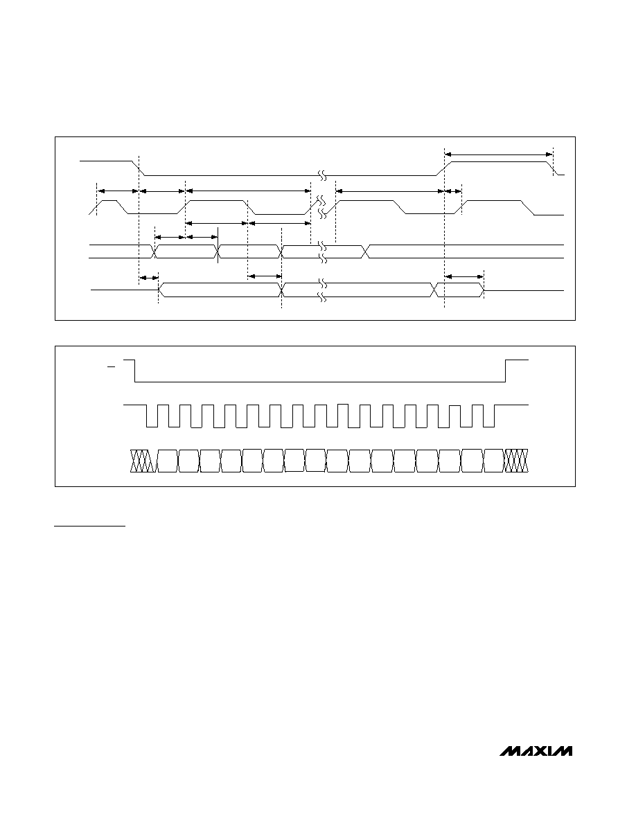
Figure 7. SPI-Interface Format
QSPI is a trademark of Motorola, Inc.
MICROWIRE is a trademark of National Semiconductor Corp.
tCSW
tCS1
tCSD
tCSH
LSB
tDO1
tCL
tCP
tCH
tDH
tDS
MSB
tCSS
tCSO
CS
SCLK
DIN
DOUT
tCSE
Figure 6. SPI-Interface Timing Diagram
发布紧急采购,3分钟左右您将得到回复。
相关PDF资料
MAX5556ESA+
IC DAC STEREO AUDIO 8-SOIC
MAX5631UCB+D
IC DAC 16BIT 32CH S&H 64-TQFP
MAX5711AUT+T
IC DAC 10BIT DUAL LP SER SOT23-6
MAX5712AUT+T
IC DAC SERIAL 12BIT 1CH SOT23-6
MAX5721AUA+T
IC DAC 10BIT DUAL LP SER 8-UMAX
MAX5725AAUP+T
IC DAC 12BIT SRL 20TSSOP
MAX5735BUTN+
IC DAC 16BIT 32CHAN SER 56-TQFN
MAX5741AUB+T
IC DAC 10BIT QUAD LP SER 10-UMAX
相关代理商/技术参数
MAX5550ETE-T
功能描述:数模转换器- DAC RoHS:否 制造商:Texas Instruments 转换器数量:1 DAC 输出端数量:1 转换速率:2 MSPs 分辨率:16 bit 接口类型:QSPI, SPI, Serial (3-Wire, Microwire) 稳定时间:1 us 最大工作温度:+ 85 C 安装风格:SMD/SMT 封装 / 箱体:SOIC-14 封装:Tube
MAX5550EVKIT+
功能描述:数据转换 IC 开发工具 MAX5548/50 Eval Kit RoHS:否 制造商:Texas Instruments 产品:Demonstration Kits 类型:ADC 工具用于评估:ADS130E08 接口类型:SPI 工作电源电压:- 6 V to + 6 V
MAX5556ESA
制造商:Maxim Integrated Products 功能描述:LOW-COST STEREO AUDIO DAC - Rail/Tube
MAX5556ESA/V+
功能描述:数模转换器- DAC Low-Cost Stereo Audio DACs RoHS:否 制造商:Texas Instruments 转换器数量:1 DAC 输出端数量:1 转换速率:2 MSPs 分辨率:16 bit 接口类型:QSPI, SPI, Serial (3-Wire, Microwire) 稳定时间:1 us 最大工作温度:+ 85 C 安装风格:SMD/SMT 封装 / 箱体:SOIC-14 封装:Tube
MAX5556ESA/V+T
功能描述:数模转换器- DAC Low-Cost Stereo Audio DACs RoHS:否 制造商:Texas Instruments 转换器数量:1 DAC 输出端数量:1 转换速率:2 MSPs 分辨率:16 bit 接口类型:QSPI, SPI, Serial (3-Wire, Microwire) 稳定时间:1 us 最大工作温度:+ 85 C 安装风格:SMD/SMT 封装 / 箱体:SOIC-14 封装:Tube
MAX5556ESA+
功能描述:音频数/模转换器 IC 24-Bit 2Ch Audio DAC RoHS:否 制造商:Texas Instruments 转换器数量: 分辨率:16 bit 接口类型:I2S, UBS 转换速率: 信噪比:98 dB 工作电源电压:5 V DAC 输出端数量:2 工作温度范围:- 25 C to + 85 C 电源电流:23 mA 安装风格:SMD/SMT 封装 / 箱体:TQFP-32 封装:Reel
MAX5556ESA+
制造商:Maxim Integrated Products 功能描述:IC DAC 24BIT 50KSPS SOIC-8
MAX5556ESA+T
功能描述:音频数/模转换器 IC 24-Bit 2Ch Audio DAC RoHS:否 制造商:Texas Instruments 转换器数量: 分辨率:16 bit 接口类型:I2S, UBS 转换速率: 信噪比:98 dB 工作电源电压:5 V DAC 输出端数量:2 工作温度范围:- 25 C to + 85 C 电源电流:23 mA 安装风格:SMD/SMT 封装 / 箱体:TQFP-32 封装:Reel